Rohloff Speedhub 500/14 twist grip for road bike handlebars
Rohloff of Fuldatal, Germany makes a 14-speed internal gear bicycle hub, controlled by a single twist grip. However, Rohloff only supplies a twist grip suitable for mounting on mountain bike handlebars, making it a challenge to use their hub on a road bike.
One possible solution is to mount Rohloff's twist grip control on a cut down MTB bar end clamped to a road stem, as shown at this photo on Sheldon Brown's web site. I used this method for a while and found it okay. One drawback was that my right knee sometimes hit the shifter when pedaling while standing (the shifter in Sheldon's photo is angled forward a bit, possibly to help alleviate this problem).
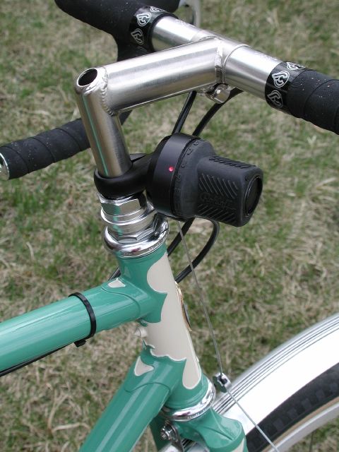
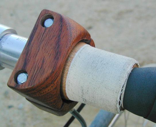
My preferred solution was to make my own twist grip to mount directly on the center section of a road handlebar, as shown below. The grip itself is hardwood (maple), lathe turned. Mounting it entailed cutting it lengthwise and gluing the two pieces together around the handlebar. White cotton tape gives a better grip than bare would.
Stationary pieces of darker wood (bubinga) clamp onto the central reinforcing sleeve of the handlebar, and serve to hold the cable housings in place.
Shifting feel is similar to that of the stock Rohloff twist grip. Wood is susceptible to water damage, but I'm not much worried about that because it hardly ever rains where I live. One obvious disadvantage of this device is the permanent (glued together around the bar) mounting, which would require making a new grip if the handlebar needed replacement.
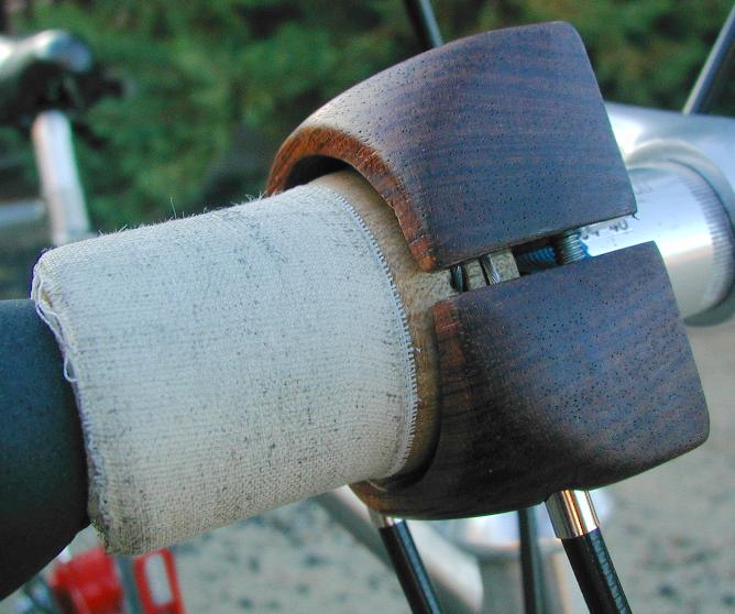
This second photo shows the cables, which run on grooves machined into the grip; the hole where the near cable disappears into the grip is visible.
Since I first set up this page, various firms have offered products for mounting Rohloff twist grips on conventional road handlebars. They weren't available when I made my grip.
I've been asked about how to make a wood grip like this. My quick answer is, don't do it unless you like doing things the hard way. But for those who want to know:
I made the cylindrical shape from solid maple, on a lathe. The portion that the cables bear on has a slightly larger diameter than the portion that you grip. The two grooves for the cables don't have to be very deep.
I bored a (approximately handlebar-sized) hole through the maple piece, using a drillpress.
I cut the maple piece lengthwise with a bandsaw. I lightly sanded the cut surfaces to make them flat in preparation for gluing later.
The final shaping of the inside surface was done with sandpaper wrapped around the handlebar. This made the surface close to cylindrical again, undoing the effect of having lost some wood to the kerf of the bandsaw blade.
Recesses for the cable ends were drilled, obliquely, into the ends of the wood pieces, with a diameter large enough to accommodate the buttons on the ends of the cables. I then drilled smaller (cable-diameter) holes obliquely from the outside (starting in the cable grooves). Getting those holes to meet the recesses properly is the fun part.
The two pieces were glued together around the handlebar. I used as little glue as I could, so it wouldn't ooze out of the joint and gum up the inside surface that bears against the handlebar.
The inner curved surfaces on the stationary pieces (bubinga wood) were made using a router and a drillpress. The rounded outside shape was made with files and sandpaper.
The main difficulty with the stationary pieces was in how they attach to the handlebar. I used two long machine screws (visible in the first photo) to clamp the pieces together, and placed a thin sheet of rubber between the wood and the handlebar to distribute the stress over the wood better and to improve the grip. Even so, that alone isn't secure enough; the pieces would turn on the handlebar. I added a third screw (in the center of the bottom piece, not visible in the photos) whose tip engages a small dimple I put in the (reinforcing sleeve of the) handlebar. With that, the wood pieces stay put when you shift.
About the hub itself:
A Speedhub has three planetary gear stages in sequence. The first two stages are identical in their gear tooth counts; they are assembled in mirror symmetry and share the same planet carrier. Each of those two stages has two different sun gears (engaging different sets of teeth on the stepped planet gears) and thus can achieve different ratios depending on which sun gear is locked to the hub's axle.
| first stage: | direct drive, or reduction | by 15/22 or 24/31 | |
| second stage: | direct drive, or increase | by 22/15 or 31/24 | third stage: | direct drive, or reduction | by 221/541 |
Labeling the various stage ratios,
  a = 15/22    b = 24/31
  c = 22/15    d = 31/24
  e = 221/541
the hub's 14 gears are achieved with these combinations:
| gear | stages | ratio |
|---|---|---|
1 |
a e |
3315/11902 |
2 |
b e |
5304/16771 |
3 |
ade |
34255/95216 |
4 |
e |
221/541 |
5 |
bce |
38896/83855 |
6 |
de |
6851/12984 |
7 |
ce |
4862/8115 |
8 |
a |
15/22 |
9 |
b |
24/31 |
10 |
ad |
155/176 |
11 |
- |
1/1 |
12 |
bc |
176/155 |
13 |
d |
31/24 |
14 |
c |
22/15 |
I've been asked how there can be a 221/541 ratio; 541 is a prime number, and no single gear in a Speedhub has a tooth count that's a multiple of 541.
The final stage uses a ring gear with 96 teeth, a sun gear with 51 teeth, and stepped planet gears with 20 and 26 teeth. See Rohloff's US patent 6,258,005 for more details.
221/541 = (26 * 51) / ((26 * 51) + (20 * 96))
The first two stages have ring gears with 90 teeth, sun gears with 35 and 42 teeth, and stepped planet gears with 24 and 32 teeth.
ratio a: 15/22 = 90 / (90 + 42)
ratio b: 24/31 = (32 * 90) / ((32 * 90) + (35 * 24))
Planetary gear ratios can be counterintuitive; see Wikipedia's Epicyclic gearing page for formulas.
Tom Ace
return to Tom's home page